IONIX SOFTWARE, INC.
This paragraph contains a brief description of the PLB Ladder Logic and Flow Logic Diagrams.
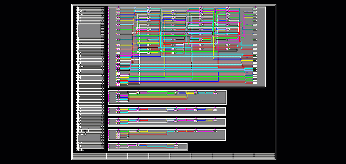
The PLB Ladder Logic and Flow Logic Diagram is a color drawing with the entire ladder logic and flow logic residing in a digital FBM. The drawing has two sections: in the left side of the drawing the ladder logic is displayed with all rungs in the same FBM. An equivalent,computer-generated, Boolean logic flow diagram is displayed on the right side of the drawing. The drawing is helpful in complex control logic of hydrogen gas compressors, furnaces or other process equipment control.

Figure 3.1
In Figure 3.1 a complete Ladder Logic and Flow Logic, which resides in a FBM, is presented. One can easily see the logic control loops.

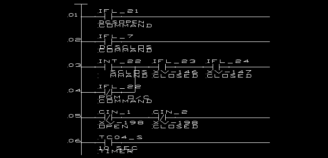
Figure 3.2
In Figure 3.2 a section of the Ladder Logic is displayed.

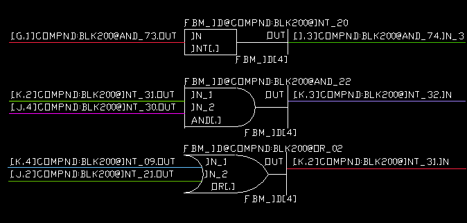
Figure 3.3
In Figure 3.3 a detailed representation of Boolean logic is displayed. One can see the inputs and outputs of the logical gates are displayed together with the sink/source paths.

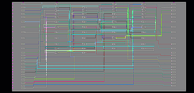
Figure 3.4
In Figure 3.4 a general view of a logic is displayed. One can see logical gates and logical blocks displayed along with their connections. Plants which are short of their Plant related logic can utilize this package to "recover" their lost documentation, and get "as-built" their flow logic and ladder logic.
Key Benefits


